|
|||||||||||||||||||||||||||||||||||||||||||||||||||||||||||||||||||||||||||||||||||||||||||||||||||||||||||||||||||||||||||||
Used Machinery Used
Air Compressors Used
Sheet Metal Brakes Used
Duct Beading Machine Used
HVAC Duct Insulation Pin Spotters Used
Pipe Equipment Used
Sheet Metal Rolls
|
Roper Whitney Sheet Metal Folders | Auto Brake AB1014K Kombi Series
Roper Whitney Autobrake Kombi Series |
||||||||||||||||||||||||||||||||||||||||||||||||||||||||||||||||||||||||||||||||||||||||||||||||||||||||||||||||||||||||||||
| AB1016K | AB1216K | AB1014K | AB1214K | |
| Bending Capacity (Mild Steel) | 16ga | 16ga | 14ga | 14ga |
| Bending Capacity (Stainless) | 20ga | 20ga | 16ga | 16ga |
| Bending Length | 122" | 147.5" | 122" | 147.5" |
| Bending Bars | 0.787", 0.390", 0.250" | 0.787", 0.390", 0.250" | 0.787", 0.390", 0.250" | 0.787", 0.390", 0.250" |
| Back Gauge Depth (Standard) | 40" | 40" | 61" | 61" |
| Back Gauge Increased (Optional) | On Request | On Request | On Request | On Request |
| Clamping Beam Opening Height | 7.3" | 7.3" | 7.3" | 7.3" |
| Clamping Beam Straight Bar Tooling | 30º | 30º | 30º | 30º |
| Segment Box and Pan Tooling Depth | 4" | 4" | 4" | 4" |
| Folding Beam Adjustment | 2" | 2" | 2" | 2" |
| Crowning of the Folding Beam | 5-Point 0"-0.030" Adjustment | 5-Point 0"-0.030" Adjustment | 5-Point 0"-0.030" Adjustment | 5-Point 0"-0.030" Adjustment |
| Working Height | 35" | 35" | 35" | 35" |
| Machine Length | 155" | 159" | 181" | 181" |
| Machine Width | 56" | 89" | 89" | 89" |
| Machine Height | 60" | 68" | 68" | 68" |
| Machine Weight | 8202lbs | 9542lbs | 10842lbs | 11250lbs |
| Shipping Weight | 8912lbs | 10022lbs | 11500lbs | 12000lbs |
| Back Gauge Servo Motor | 3/4 hp | 3/4 hp | 3/4 hp | 3/4 hp |
| Kombi Beam Rotation Motor | 1 hp | 1 hp | 1 hp | 1 hp |
| Clamping Beam Motor | 1.5 hp | 2 hp | 2 hp | 2 hp |
| Bending Beam Motor | 1.5 hp | 2 hp | 2 hp | 3 hp |
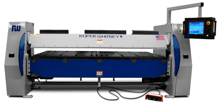
Roper Whitney 1009K Precision Autobrake
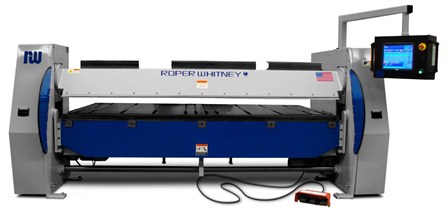
The AB1009K Precision Autobrake provides precision and repeatability when forming up to 10 feet of 9 gauge mild steel or lighter materials. This sheet metal brake is a high speed solution to make a variety of bends while maintaining a high quality level in the end product. The backgauge provides accurate part location through the use of servo drives and is expandable with optional backgauge extensions. The rigid design includes automatic crowning adjustments to ensure accurate bending regardless of raw material stresses. Tooling options are provided to help customize to your specific needs, and can be provided in tool steel or hardened.
Standard Features:
– 30° Clamping Beam
– Hardened 6.3” Quick-Change Kombi Box Tooling
– Hardened Upper Jaw, Lower Jaw & Bending Bars
– Automatic Crowning Adjustment
– Automatic Material Thickness Adjustment
– 61” Backgauge
– Solid Backgauge Fingers
– Adjustable Height Backgauge
– Side Mounted Squaring-Arm
– Automatic Pivot Point Adjustment
– Segmented Bending Beam & Lower Jaw Tooling
– 18.5” Touchscreen Monitor w/ Synergy Control
– Konnect Software Package (Included While Under Warranty)
Options & Upgrades:
– 0.984” / 25 mm Bending Bar
– Left, Right or U-Shaped Backgauge Extensions
– Spring Steel Backgauge Fingers
– Backgauge Ball Transfers (Steel or Acetyl)
– 10’ Safety Laser Scanner
– Second Operator Foot Pedal (Front or Rear)
– Rolling Foot Pedal
– Konstruct Offline Software
The Autobrake design is a plate and weldment steel construction, delivering superior performance and features in a simplified rigid design. End housings are a plate-type construction bringing drive components close together for improved stiffness and performance. Actuating mechanisms are secured in rigid mounts at the outside of the housings, allowing easy maintenance. The bending beam is powered by dual direct drive motors to ensure maximum power and efficiency.
Clamping and hemming capabilities come standard and are already included in the software. Clamping and hemming power is delivered to the clamp jaws by a series of spring washers to provide variable clamping pressures with a shock-absorbing end stop. This provides reliable clamping pressure to create open, tear drop, and closed hems to best suit your needs.
This sheet metal brake comes standard with a rotating Kombi beam. This unique tooling assembly adds to the machines straight and box folding capabilities to produce more complex shapes in less time. It handles a wide range of materials, easily closes hems and withstands the force generated by maximum capacity forming operations. Box tooling is equipped with Roper Whitney’s quick change design allowing for maximum up time and minimized change over time.
Multiple options can be added, at the time of purchase, to maximize the equipment versatility. These options include segmented lower and bend tooling, automated pivot point adjustment, automated up/down backgauge, back gauge extensions for rear operation, and much more. Ask your Roper Whitney sales representative for details.
The Synergy control offers high speed versatility to an end user. It offers multiple methods of programming from simple line-by-line to draw-to-auto program. Its network capabilities allow for multiple options, such as; Konnect, Konstruct, Mobile Konstruct, and overall shop management through linking multiple machines.
Specifications:
Bending Capacity (Mild Steel): 9 ga
Bending Capacity (Stainless): 11 ga - up to 90°, 12ga - past 90°
Bending Length: 126 in
Bending Bars: 1.38" (35mm) bending bar x 150"
& .500" (12mm) bending bar x 150"
Crowning of the Folding Beam: 3-Point 0”-0.030” Adjustment
Folding Beam Adjustment: 2 in
Clamping Beam Opening Height: 7.3 in
Clamping Beam Tooling: 30 Degrees
Back gauge Depth (Standard): 61 in
Working Height: 34 in
Back Gauge Motor: 2.4 hp / 1.8 KW Servo
Clamping Beam Motor: 5.4 hp / 4KW
Bending Beam Motor: Dual 10.8 hp / 8KW
Maximum Depth of Box: (4 Sides) 6.3in
Machine Weight: 17,500 lbs.
Machine Dimensions: 180 x 96 x 84 in
Speeds:
Clamping Beam Speed: 2.5” per second
Folding Beam Speed: 80 degrees per second
Back gauge Speed: (0.25” to 61”) 2.5 seconds
Return to the Folders Page
Return to the New Machinery Page
Return to the Home
Page
 Contact Us | Site
Map | ©2004 Cincinnati Precision Machinery, Inc. All rights
reserved.
Contact Us | Site
Map | ©2004 Cincinnati Precision Machinery, Inc. All rights
reserved.